Contaminant Comparison Chart

For a complete list of contaminants that PUR filters reduce, please view our Performance Data Sheets here.


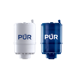
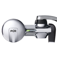
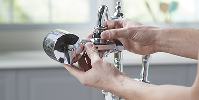
PUR & PUR PLUS FAUCET FILTERS
RF3375/RF9999

View Filters

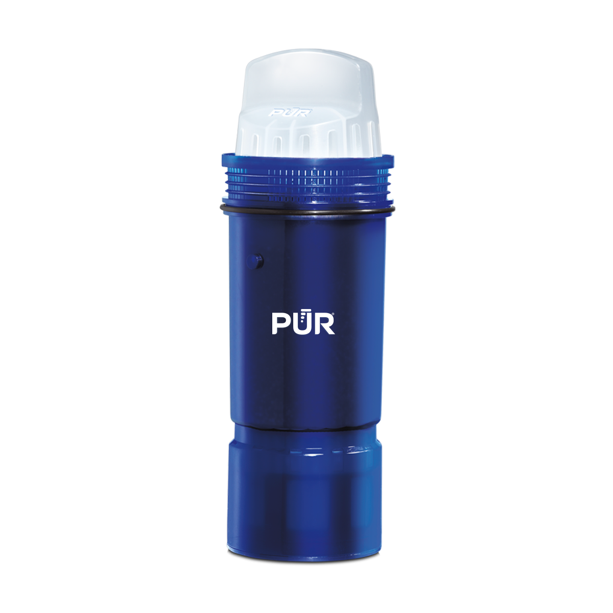
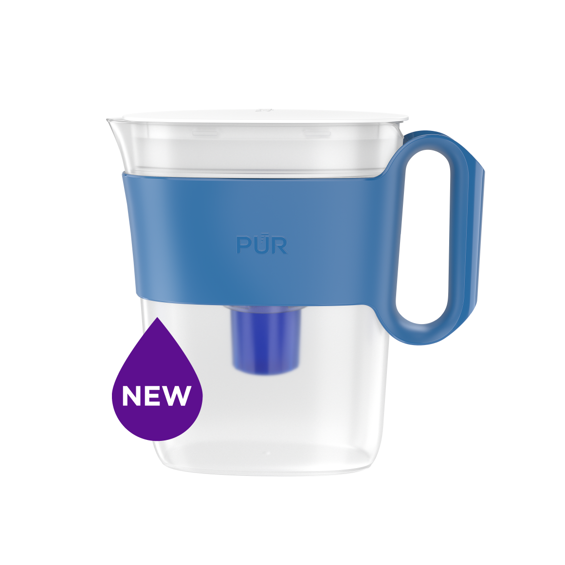
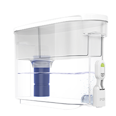
PUR PLUS PITCHER FILTERS
PPF951K

View Filter

PUR BASIC PITCHER FILTERS
PPF900Z

View Filter


Vs. Brita*

Lead ✓ ✓
Microplastics ✓ ✓
Mercury ✓ ✓ ✓
Chlorine Taste & Odor ✓ ✓ ✓
DEET ✓
TTHM ✓

PUR’s Filtration Systems Are Certified By NSF And WQA For Their Contamination Reduction. WQA certifications as of 5/27/21 for Faucet filter models RF-3375 and RF-9999.

¹ Certified to reduce 10X more chemical and physical substances than Brita’s® leading pitcher filter.
² Certified to reduce 3X more chemical and physical substances than Brita’s® leading pitcher filter.
³ Certified to reduce 2X more chemical and physical substances than Brita’s® leading pitcher filter.
*Versus best-selling Brita® pitcher filter OB03. Brita® is a trademark of Brita LP.
**Like other leading brands, PUR does not filter microbes. As of 3/1/23 Brita® and ZeroWater® were not certified to filter microbes. Brita® is a trademark of Brita LP. ZeroWater® is a trademark of Zero Technologies, LLC..
 

PUR & PUR PLUS FAUCET FILTERS


PUR & PUR PLUS FAUCET FILTERS
RF3375/RF9999

View Filters


Vs. Brita*

Lead ✓
Microplastics ✓
Mercury ✓
Chlorine Taste & Odor ✓
DEET ✓
TTHM ✓

PUR’s Filtration Systems Are Certified By NSF And WQA For Their Contamination Reduction. WQA certifications as of 5/27/21 for Faucet filter models RF-3375 and RF-9999.

¹ Certified to reduce 10X more chemical and physical substances than Brita’s® leading pitcher filter.
² Certified to reduce 3X more chemical and physical substances than Brita’s® leading pitcher filter.
³ Certified to reduce 2X more chemical and physical substances than Brita’s® leading pitcher filter.
*Versus best-selling Brita® pitcher filter OB03. Brita® is a trademark of Brita LP.
**Like other leading brands, PUR does not filter microbes. As of 3/1/23 Brita® and ZeroWater® were not certified to filter microbes. Brita® is a trademark of Brita LP. ZeroWater® is a trademark of Zero Technologies, LLC..


PUR PLUS PITCHER FILTERS


PUR PLUS PITCHER FILTERS
PPF951K

View Filter


Vs. Brita*

Lead ✓
Microplastics ✓
Mercury ✓
Chlorine Taste & Odor ✓
DEET
TTHM

PUR’s Filtration Systems Are Certified By NSF And WQA For Their Contamination Reduction. WQA certifications as of 5/27/21 for Faucet filter models RF-3375 and RF-9999.

¹ Certified to reduce 10X more chemical and physical substances than Brita’s® leading pitcher filter.
² Certified to reduce 3X more chemical and physical substances than Brita’s® leading pitcher filter.
³ Certified to reduce 2X more chemical and physical substances than Brita’s® leading pitcher filter.
*Versus best-selling Brita® pitcher filter OB03. Brita® is a trademark of Brita LP.
**Like other leading brands, PUR does not filter microbes. As of 3/1/23 Brita® and ZeroWater® were not certified to filter microbes. Brita® is a trademark of Brita LP. ZeroWater® is a trademark of Zero Technologies, LLC..


PUR BASIC PITCHER FILTERS


PUR BASIC PITCHER FILTERS
PPF900Z

View Filter


Vs. Brita*

Lead
Microplastics
Mercury ✓
Chlorine Taste & Odor ✓
DEET
TTHM

PUR’s Filtration Systems Are Certified By NSF And WQA For Their Contamination Reduction. WQA certifications as of 5/27/21 for Faucet filter models RF-3375 and RF-9999.

¹ Certified to reduce 10X more chemical and physical substances than Brita’s® leading pitcher filter.
² Certified to reduce 3X more chemical and physical substances than Brita’s® leading pitcher filter.
³ Certified to reduce 2X more chemical and physical substances than Brita’s® leading pitcher filter.
*Versus best-selling Brita® pitcher filter OB03. Brita® is a trademark of Brita LP.
**Like other leading brands, PUR does not filter microbes. As of 3/1/23 Brita® and ZeroWater® were not certified to filter microbes. Brita® is a trademark of Brita LP. ZeroWater® is a trademark of Zero Technologies, LLC..


What Is a Heat Transfer Tank and How Does It Work?

A Heat Transfer Tank is more than a metal vessel with a heating coil. It is a controlled system for transferring thermal energy into liquids, slurries, or process materials. Frank P. Incropera, a respected heat-transfer educator, states, “Heat transfer is thermal energy in transit due to a spatial temperature difference.” This principle explains the tank’s basic purpose. A heated fluid moves through a jacket or internal coil, while the stored product absorbs energy through the tank wall.

The process sounds simple. It is not always simple.

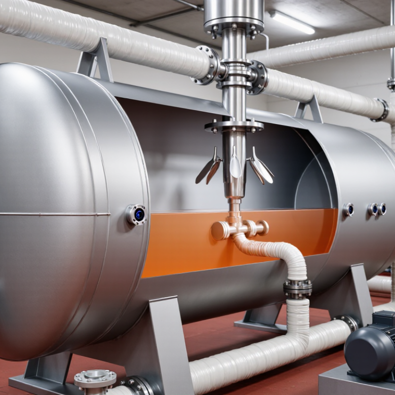
Inside a typical Heat Transfer Tank, sensors monitor temperature near the outlet, tank wall, and product zone. A pump may circulate the heating medium to reduce cold spots. An agitator improves mixing and prevents thick materials from settling. Stainless steel surfaces often support clean operation, but material selection still depends on pressure, temperature, corrosion, and fluid compatibility.

Good design begins with the product, not the tank alone. Water heats quickly. Oil, syrup, and viscous chemicals behave differently. Their flow resistance can slow circulation and create uneven temperatures. Insulation reduces heat loss around the shell, fittings, and access cover. Even small gaps can waste energy.

This guide examines how a Heat Transfer Tank works, how heat moves through its components, and which operating details influence performance. It also considers common design weaknesses, because real systems are rarely perfect. A temperature display may look accurate while measuring only one small area. A powerful heater may still produce poor results without proper circulation. Understanding these limitations helps engineers, operators, and buyers make safer, more reliable decisions.

What Is a Heat Transfer Tank and How Does It Work?

Definition and Core Purpose of a Heat Transfer Tank

A heat transfer tank is an insulated vessel designed to move thermal energy into or out of a process. It may contain water, thermal oil, or another engineered fluid. Heat travels through a coil, jacket, or internal exchanger, rather than mixing directly with the process material. The tank therefore supports controlled heating, cooling, or temporary thermal storage.

Its core purpose is stability. A well-designed tank keeps temperature changes gradual and predictable. Operators can heat a batch of liquid, hold it at a set temperature, and transfer energy when demand rises. In a real plant, this can reduce burner cycling and protect sensitive materials from hot spots. It is not merely a large container.

The U.S. Department of Energy’s Industrial Decarbonization Roadmap states that process heating represents about 51% of energy use in American manufacturing. The International Energy Agency also reports that industry consumes roughly 37% of global final energy. These figures explain why thermal control deserves engineering attention, not guesswork.

Tank volume, fluid properties, insulation, residence time, and exchanger area all affect performance. A larger tank is not automatically better. Oversizing can increase heat loss and slow response.

Field measurements often differ from design calculations. Fouling, poor insulation, and uneven circulation can quietly reduce efficiency. The calculation is rarely perfect. Engineers should verify inlet temperature, outlet temperature, flow rate, and actual heat duty during operation. These checks make the tank’s real purpose visible: delivering usable heat at the required time, temperature, and rate.

Main Components and Their Functions

What Is a Heat Transfer Tank and How Does It Work?

Main Components and Their Functions

A heat transfer tank stores hot or chilled fluid and moves thermal energy when demand changes. Its shell holds the working fluid, while insulation slows heat loss through the walls. The tank may contain water, glycol mixtures, or another approved heat-transfer medium. The International Energy Agency’s Energy Efficiency 2023 report notes that buildings use about 30% of global final energy. Better thermal storage can reduce unnecessary heating and cooling demand.

The heat exchanger transfers energy between separate fluid circuits. Plates, coils, or internal tubes provide this contact without mixing the fluids. Circulation pumps control flow through the tank. Their speed affects temperature stability, pressure, and electricity use. Temperature sensors monitor supply and return conditions. A control valve then adjusts flow when readings move beyond the selected range. Small errors matter.

Expansion vessels absorb fluid expansion during heating. Pressure relief devices protect the tank if pressure rises unexpectedly. A drain connection supports maintenance and safe fluid replacement. The U.S. Department of Energy’s 2023 Thermal Energy Storage Technology Strategy Assessment identifies load shifting as a major storage benefit. However, a tank is not automatically efficient. Poor insulation, oversized pumps, or badly placed sensors can waste energy. In field inspections, sensor drift is an easy problem to overlook. The design may look correct, yet perform unevenly.

How Heat Transfer Tanks Move and Exchange Heat

A heat transfer tank stores and moves thermal energy between separate fluid circuits. One fluid carries heat, while another receives it through a coil, jacket, or internal heat exchanger. The fluids usually remain separated. Only heat crosses the metal surface.

A pump pushes the hot fluid through the transfer path. As it flows, heat travels from the warmer fluid into the cooler tank contents. Conduction moves heat through the exchanger wall, while convection circulates warmth inside the tank. Sensors monitor temperature near the inlet, outlet, and tank center. A controller can slow the pump when the target temperature is reached. In practical inspections, uneven heating often points to trapped air, weak circulation, or mineral buildup. Small details matter. Tank layering can also develop, leaving the upper section hot while the bottom remains cool. That condition wastes energy and may confuse a single temperature sensor.

Tips: Check flow direction before testing performance. Confirm both circuits have adequate pressure. Clean heat-transfer surfaces on a planned schedule. Insulate exposed pipes, but never cover safety valves or inspection points. A quick temperature reading is useful, but it does not reveal every problem. Comparing inlet and outlet temperatures gives better evidence. Operators should record these readings under similar conditions, because changing flow rates can make a healthy system appear inefficient. Certain assumptions deserve review. A larger pump is not always better. Excessive flow may reduce transfer time and increase wear.

Common Heating and Cooling Methods

What Is a Heat Transfer Tank and How Does It Work?

Common Heating and Cooling Methods

A heat transfer tank moves thermal energy between a process fluid and a working medium. The fluids usually remain separated by a metal wall, coil, or jacket. This design reduces contamination and supports steady temperature control. Sensors monitor temperature, pressure, and flow. A controller then adjusts the heating or cooling source.

Electric immersion heaters provide direct, accurate heating for smaller tanks. Hot water systems offer gentle heating and work well with sensitive fluids. Steam heats quickly, but it needs careful pressure control and condensate drainage. Thermal oil can reach higher temperatures without high system pressure. Each method has limits. Electric systems may increase operating costs, while steam systems need more maintenance.

Cooling commonly uses chilled water, glycol mixtures, or refrigerated circuits. Chilled water suits moderate temperature reduction. Glycol helps prevent freezing in colder environments. Refrigerated systems deliver lower temperatures but consume more energy. In field inspections, poor insulation often causes unexpected heat loss. A tank may appear powerful, yet its exposed pipes waste energy. That detail is easy to miss.

No method is perfect. Tank material, fluid viscosity, temperature range, and cleaning requirements should guide the selection. Uneven circulation can create hot or cold zones. Proper pump sizing matters. Engineers should test the actual fluid, not only rely on catalog data. Small design changes, such as better baffles or insulation, can improve stability significantly.

Applications, Benefits, and Operating Considerations

A heat transfer tank stores and circulates a fluid that moves heat between equipment and a process. It may contain water, thermal oil, or another approved medium. A pump sends the heated fluid through coils, jackets, or external heat exchangers. The tank then receives the cooler return fluid. This creates a controlled heating or cooling loop.

These systems serve food processing, chemical production, drying equipment, building services, and industrial washing lines. They can maintain steadier temperatures than direct heating alone. Operators may also reduce hot spots, product damage, and energy waste. In practice, a well-sized tank helps stabilize demand when equipment loads change quickly. The benefit is practical.

Operating results depend on correct sizing and disciplined monitoring. Engineers should check fluid compatibility, operating pressure, temperature limits, insulation, and expansion space. A blocked filter can reduce flow and create uneven heating. Air pockets may cause pump noise or weak heat transfer. Regular checks should include leaks, valve movement, sensor accuracy, and fluid condition. Keep records.

Safety controls need independent high-temperature and low-level protection. Operators should confirm that relief devices discharge safely and remain accessible. Insulation lowers surface temperatures and protects workers near the tank. However, insulation can hide corrosion or small leaks, so visual inspections still matter. No tank is maintenance-free. Real operating conditions often differ from design assumptions, and that difference deserves review.