




Contaminant Comparison Chart

For a complete list of contaminants that PUR filters reduce, please view our Performance Data Sheets here.


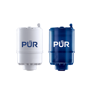
PUR & PUR PLUS FAUCET FILTERS
RF3375/RF9999

View Filters

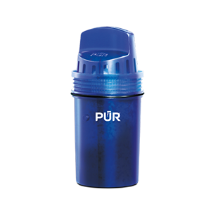
PUR PLUS PITCHER FILTERS
PPF951K

View Filter

PUR BASIC PITCHER FILTERS
PPF900Z

View Filter


Vs. Brita*

Lead
Microplastics
Mercury
Chlorine Taste & Odor
DEET
TTHM

PUR’s Filtration Systems Are Certified By NSF And WQA For Their Contamination Reduction. WQA certifications as of 5/27/21 for Faucet filter models RF-3375 and RF-9999.

¹ Certified to reduce 10X more chemical and physical substances than Brita’s® leading pitcher filter.
² Certified to reduce 3X more chemical and physical substances than Brita’s® leading pitcher filter.
³ Certified to reduce 2X more chemical and physical substances than Brita’s® leading pitcher filter.
*Versus best-selling Brita® pitcher filter OB03. Brita® is a trademark of Brita LP.
**Like other leading brands, PUR does not filter microbes. As of 3/1/23 Brita® and ZeroWater® were not certified to filter microbes. Brita® is a trademark of Brita LP. ZeroWater® is a trademark of Zero Technologies, LLC..
 

PUR & PUR PLUS FAUCET FILTERS


PUR & PUR PLUS FAUCET FILTERS
RF3375/RF9999

View Filters


Vs. Brita*

Lead
Microplastics
Mercury
Chlorine Taste & Odor
DEET
TTHM

PUR’s Filtration Systems Are Certified By NSF And WQA For Their Contamination Reduction. WQA certifications as of 5/27/21 for Faucet filter models RF-3375 and RF-9999.

¹ Certified to reduce 10X more chemical and physical substances than Brita’s® leading pitcher filter.
² Certified to reduce 3X more chemical and physical substances than Brita’s® leading pitcher filter.
³ Certified to reduce 2X more chemical and physical substances than Brita’s® leading pitcher filter.
*Versus best-selling Brita® pitcher filter OB03. Brita® is a trademark of Brita LP.
**Like other leading brands, PUR does not filter microbes. As of 3/1/23 Brita® and ZeroWater® were not certified to filter microbes. Brita® is a trademark of Brita LP. ZeroWater® is a trademark of Zero Technologies, LLC..


PUR PLUS PITCHER FILTERS


PUR PLUS PITCHER FILTERS
PPF951K

View Filter


Vs. Brita*

Lead
Microplastics
Mercury
Chlorine Taste & Odor
DEET
TTHM

PUR’s Filtration Systems Are Certified By NSF And WQA For Their Contamination Reduction. WQA certifications as of 5/27/21 for Faucet filter models RF-3375 and RF-9999.

¹ Certified to reduce 10X more chemical and physical substances than Brita’s® leading pitcher filter.
² Certified to reduce 3X more chemical and physical substances than Brita’s® leading pitcher filter.
³ Certified to reduce 2X more chemical and physical substances than Brita’s® leading pitcher filter.
*Versus best-selling Brita® pitcher filter OB03. Brita® is a trademark of Brita LP.
**Like other leading brands, PUR does not filter microbes. As of 3/1/23 Brita® and ZeroWater® were not certified to filter microbes. Brita® is a trademark of Brita LP. ZeroWater® is a trademark of Zero Technologies, LLC..


PUR BASIC PITCHER FILTERS


PUR BASIC PITCHER FILTERS
PPF900Z

View Filter


Vs. Brita*

Lead
Microplastics
Mercury
Chlorine Taste & Odor
DEET
TTHM

PUR’s Filtration Systems Are Certified By NSF And WQA For Their Contamination Reduction. WQA certifications as of 5/27/21 for Faucet filter models RF-3375 and RF-9999.

¹ Certified to reduce 10X more chemical and physical substances than Brita’s® leading pitcher filter.
² Certified to reduce 3X more chemical and physical substances than Brita’s® leading pitcher filter.
³ Certified to reduce 2X more chemical and physical substances than Brita’s® leading pitcher filter.
*Versus best-selling Brita® pitcher filter OB03. Brita® is a trademark of Brita LP.
**Like other leading brands, PUR does not filter microbes. As of 3/1/23 Brita® and ZeroWater® were not certified to filter microbes. Brita® is a trademark of Brita LP. ZeroWater® is a trademark of Zero Technologies, LLC..


How to Wire an LED Rocker Switch?

Wiring a Led Rocker Switch can look simple, but the small terminals often cause expensive mistakes. An illuminated switch may control lights, fans, pumps, or other low-voltage accessories. Its internal design is not always identical. Some models use two terminals, while others include separate power, load, ground, and illumination connections.

A reliable installation begins with the switch diagram, not guesswork. Disconnect the power source before touching any wire. Inspect the terminal labels, then compare them with the manufacturer’s instructions. A multimeter can confirm continuity when the switch is off and on. This quick test often reveals whether the chosen terminal controls the load or only the indicator light.

Keep the circuit protected. A correctly sized fuse should sit close to the battery or power supply. Use wire suitable for the expected current, and secure every connection with a crimp terminal, soldered joint, or approved connector. Loose copper strands can create heat behind the panel. That detail is easy to miss.

The wiring path usually runs from positive power through the fuse, into the switch, and onward to the accessory. The accessory then returns to a suitable ground. Some illuminated switches need a separate ground wire for the lamp. Others illuminate only when the load is powered. Check this carefully.

There is no universal color code. Red is commonly positive, but installers should never trust color alone. Test before energizing. A wiring diagram may seem obvious, yet one reversed terminal can leave the accessory working while the light stays dark. That is a useful reminder: confirm each connection instead of relying on assumptions.

How to Wire an LED Rocker Switch?

Identify the LED Rocker Switch Terminals and Circuit Requirements

How to Wire an LED Rocker Switch?

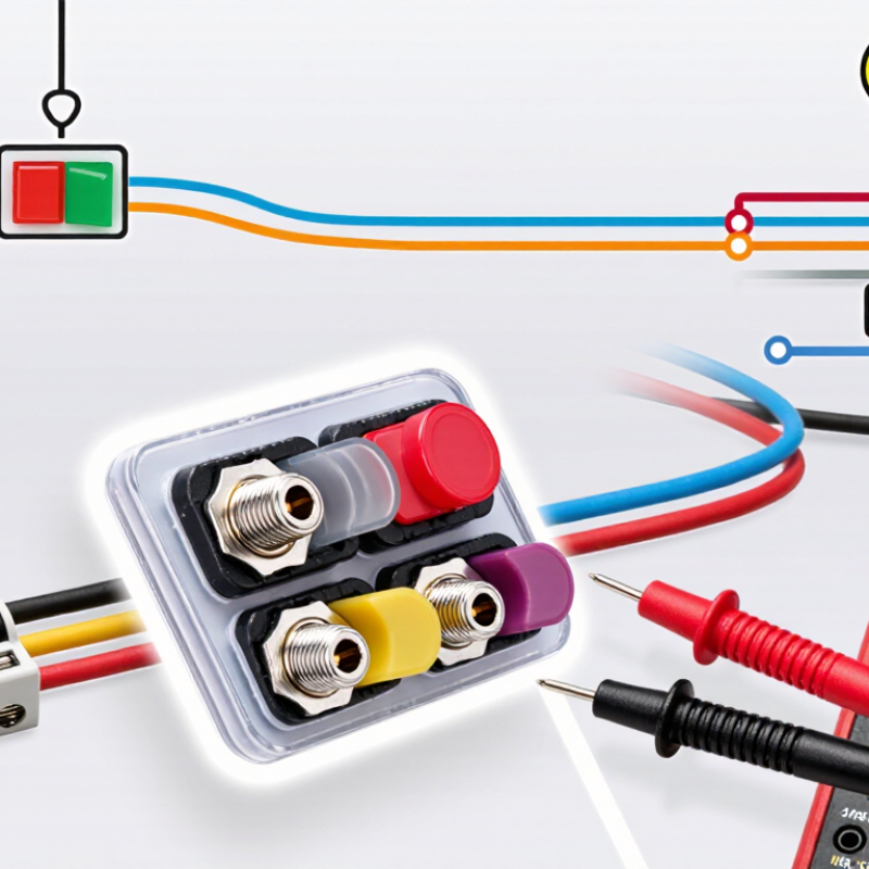
Before wiring an LED rocker switch, identify every terminal carefully. Common terminals include power input, load output, ground, and LED negative. Some switches combine the LED ground with the circuit ground. Others use separate LED terminals. Never assume the layout is universal. Check the terminal markings or the manufacturer’s wiring diagram.

The circuit must match the switch’s voltage and current ratings. A 12-volt switch should not connect directly to a higher-voltage supply. Connect the power terminal to the fused positive source. Connect the load terminal to the device’s positive wire. Attach the ground terminal to a clean chassis point or the supply negative. The LED may need its own positive and negative connections. Confirm polarity before applying power. The lamp stays dark.

Use a fuse close to the power source. Select its rating according to the load and wire capacity, not personal preference. I once tested a switch without checking its internal LED polarity. The switch worked, but the indicator did not. That small mistake cost extra time. Do not guess. Use a multimeter to identify continuity and terminal behavior, especially with SPDT switches. Keep wire insulation away from sharp panel edges. A loose crimp can create heat later. Recheck every connection with the power disconnected, then test the circuit under its normal load.

How to Wire an LED Rocker Switch?

For a typical three-terminal illuminated rocker switch, connect the power supply positive to the switch input terminal, the load positive to the output terminal, and the LED ground terminal to the power supply negative. Always verify the terminal markings and voltage rating before wiring.

Values are based on a target LED current of approximately 20 mA and typical forward voltages of about 2.0 V for red or green LEDs and 3.0 V for blue or white LEDs. Many illuminated rocker switches include an internal resistor, so use the switch’s rated voltage and do not add another resistor unless the datasheet requires it.

Gather the Tools and Plan the Wiring Layout

Before wiring an LED rocker switch, gather the right tools and map the circuit clearly. You will need wire strippers, crimpers, a digital multimeter, insulated connectors, heat-shrink tubing, and correctly rated wire. Keep an inline fuse close to the power source. A small screwdriver and cable ties can also improve the installation. Keep the power source disconnected. Check the switch diagram carefully, because terminal labels and LED connections are not universal. Some switches use separate terminals for power, load, ground, and illumination.

Sketch the layout before cutting any wire. Mark the positive source, fuse, switch, load, and negative return. The switch should interrupt the positive lead, while the load returns to the negative side. If the LED needs a separate ground, draw that connection independently. Measure each wire along its actual route, including bends and service loops. Leave enough length to remove the switch later. I once planned a layout too tightly, and one connector pulled loose during testing. That mistake was avoidable. Use different wire colors or small labels to identify each connection. Confirm polarity with the multimeter before applying power. Test continuity with the circuit isolated, then inspect every crimp for movement. A neat layout is helpful, but electrical accuracy matters more than appearance.

Connect the Power, Load, Ground, and LED Wires

How to Wire an LED Rocker Switch?

An illuminated rocker switch usually has separate terminals for power, load, ground, and the LED circuit. Disconnect the battery or supply before touching any wires. Connect fused positive power to the switch’s power terminal. Connect the load terminal to the lamp, fan, or accessory positive wire. Attach ground to a clean chassis point or the designated negative terminal. For a five-terminal switch, connect LED positive to power and LED negative to ground, unless its diagram specifies a shared load connection. Terminal layouts vary, so test with a multimeter instead of trusting terminal position.

Use wire rated for the load current, not merely the switch size. Place the fuse close to the power source. NFPA’s 2015–2019 analysis found electrical distribution and lighting equipment involved in 24% of reported home fires, making protection more than a cosmetic detail. IEC 60204-1 also stresses protective bonding and overcurrent protection in machinery circuits. In workshop testing, loose crimp joints often heat before a fuse reacts. That is easy to miss.

Tips: Label every wire before installation. Check polarity with a multimeter. Keep LED wires away from hot metal and moving parts. If the LED stays dark, reverse only its polarity if the switch allows it; do not guess. A common workshop mistake is confusing the ground terminal with the load terminal, causing a brief spark. Recheck the pin diagram, fuse rating, and current draw before energizing the circuit.

Install the Switch and Secure Every Connection

How to Wire an LED Rocker Switch?

An LED rocker switch can tidy a control panel, but every connection must be secure. Disconnect the power source before touching the wiring. Check the switch terminal diagram carefully, because layouts can vary between models. Use a multimeter to identify the power, load, and ground terminals. Do not rely only on terminal positions.

Connect the fused positive wire to the switch input. Attach the output wire to the light or accessory. Connect the LED ground wire to a suitable negative point when the switch uses a separate ground terminal. Crimp each terminal firmly, then tug it gently. Add heat-shrink tubing where moisture or vibration may reach the joint. Leave enough wire for movement, but avoid loose loops near sharp edges. A neat installation is safer and easier to inspect. I once left one wire slightly short; it worked, but the strain made the connection unreliable.

Tips: Place the fuse close to the power source. Match the fuse rating to the wire and accessory. Label each wire before installation. Test continuity with power disconnected, then restore power briefly. If the LED stays dark, check polarity and ground before replacing parts. Recheck the terminals after the first use, especially in a vibrating vehicle or outdoor enclosure. Some switches include internal resistors, while others require an external one. Never assume. Verify the specifications.

How to Wire an LED Rocker Switch? - Install the Switch and Secure Every Connection

Step / Area Connection or Specification Recommended Action Verification Point
1. Disconnect power Battery, power supply, or circuit source Turn off the supply and disconnect the negative battery cable when working on a vehicle circuit. Use a multimeter to confirm that no voltage is present at the wires.
2. Identify the switch terminals Common illuminated rocker switches may have power/input, accessory/output, ground, and sometimes a separate illumination terminal. Read the terminal markings or wiring diagram supplied with the switch. Do not rely only on terminal position or wire color. Check continuity with the switch in the OFF and ON positions before installation.
3. Select the circuit voltage The switch LED and switch contact rating must match the system voltage and load requirements. Confirm whether the switch is intended for a 12 V DC, 24 V DC, or another electrical system before wiring. Verify the printed rating on the switch against the measured supply voltage.
4. Install circuit protection Fuse or circuit breaker placed close to the power source Choose protection based on the wire ampacity and the connected load. The protective device should be installed in the positive supply conductor. Confirm that the fuse rating does not exceed the safe capacity of the wiring.
5. Connect the power input Fused positive supply wire to the switch input or power terminal Route the protected positive wire to the terminal marked for incoming power. Check that the wire is connected to the correct terminal and cannot contact adjacent terminals.
6. Connect the load output Switch output terminal to the positive input of the lamp, motor, fan, or other load Use a wire size suitable for the load current and the total wire length. With the switch ON, voltage should be present at the load’s positive terminal.
7. Connect the LED ground Ground terminal to the supply negative or a verified chassis ground Use a clean, secure grounding point. Remove paint or corrosion where a chassis connection is used, then protect the joint against corrosion. Measure low resistance between the ground terminal and the supply negative with power disconnected.
8. Handle separate illumination wiring Some switches provide a dedicated terminal for an LED that is on only when the circuit or lighting input is active. Connect the separate illumination terminal only according to the switch diagram. Some LED switches include internal current limiting; others require an external resistor or driver. Confirm the LED behavior in both the ON and OFF switch positions without exceeding its rated voltage.
9. Prepare wire ends Stripped conductor, crimp terminal, or screw-terminal connection Strip only the required length, avoid cutting wire strands, and use a terminal size that matches the conductor and stud. Perform a gentle pull test; the conductor should remain firmly held without exposed loose strands.
10. Secure every connection Crimped, soldered-and-insulated, or properly tightened terminal joints Use heat-shrink tubing or an appropriately rated insulated connector. Keep terminals covered and provide strain relief. Inspect for exposed copper, loose hardware, damaged insulation, and wires that can rub against sharp edges.
11. Mount the rocker switch Panel cutout, retaining clips, or mounting hardware Use the switch’s specified cutout dimensions and leave enough clearance behind the panel for terminals and wire bend radius. Confirm that the switch is fully seated, stable, and not strained by the connected wires.
12. Test the completed circuit OFF position, ON position, LED indication, and load operation Reconnect power, operate the switch, and observe the load and indicator. Stop immediately if wiring heats, smells, sparks, or trips the protective device. The load should operate only as intended, the LED should show the correct status, and no terminal should become unusually warm.
13. Final safety check Cable routing, insulation, polarity, and circuit protection Secure wires away from heat, moving parts, moisture, and sharp metal. Recheck polarity and replace any damaged insulation. The installation remains secure after gentle movement and does not place tension on the switch terminals.
Important: Terminal layouts, LED polarity, voltage ratings, and current ratings vary by switch design. Always follow the markings or wiring diagram for the specific switch, and use a qualified electrician or technician when the circuit voltage or load presents a safety risk.

Test the Circuit and Troubleshoot Common Wiring Problems

After wiring an LED rocker switch, test the circuit before mounting everything permanently. Disconnect power and inspect each terminal against the switch diagram. A three-pin switch may use power, load, and ground connections. A four-pin model may separate the LED ground. Do not assume similar-looking terminals share the same function.

Reconnect power through the correct fuse. Press the switch and measure voltage across the load terminals with a multimeter. The reading should change between near-zero and supply voltage. Then check the LED separately. If the load works but the LED stays dark, inspect its ground and polarity.

If nothing works, check the fuse, battery supply, crimp connections, and ground point. A switch that remains on may have the input and output wires reversed, or it may use a different internal switching design. Flickering often indicates a loose crimp or weak ground.

Heat around a terminal signals excessive resistance and requires immediate power removal. Keep wires away from sharp edges and moving parts.

I once trusted a clean-looking connector that was only gripping insulation. It passed a quick visual check, but failed under vibration. A gentle wire-pull test revealed the mistake. Still, this test is not enough; measure voltage under load. Recheck every connection after the first operating cycle. Some problems appear only when the lamp or motor draws current.